Scope of Application
The GCK type low-voltage withdrawable switchgear assembly (functionally equivalent to or better than GCL type, hereinafter referred to as “switchgear”) is designed for AC 380V, three-phase four-wire or three-phase five-wire systems. It is used in power plants, substations, industrial and mining enterprises, and high-rise buildings for receiving power, feedering power, reactive power compensation, energy metering, lighting, and centralized motor control.
This product complies with the following standards: GB7251 Low-voltage switchgear and controlgear assemblies JB/T9661 Low-voltage withdrawable switchgear assemblies IEC60439-1 Low-voltage switchgear and controlgear assemblies
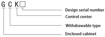
Model and Its Meaning
Normal Operating Conditions
1. Altitude: ≤ 2000 m
2. Ambient temperature: -5℃ ~ +40℃; daily average temperature ≤ +35℃
3. Relative humidity: ≤ 50% at +40℃; higher humidity is allowed at lower temperatures (e.g., 90% at +20℃)
4. Environment: Free from fire/explosion hazards, severe pollution, chemical corrosion, and severe vibration
5. Installation tilt: ≤ 5° from vertical
6. Transport/storage temperature: -25℃ ~ +55℃; up to +70℃ for short periods (≤ 24 hours)
7. If these conditions cannot be met, please consult our company at the time of ordering.
Main Technical Parameters
1. Rated insulation voltage: 660V, 1000V
2. Rated working voltage: 380V, 660V
3. Auxiliary circuit rated voltage: AC 220V, 380V; DC 110V, 220V
4. Rated frequency: 50Hz (60Hz optional)
5. Rated current:
Horizontal busbar: ≤ 3150A
Vertical busbar: 630A, 800A, 1200A
6. Rated short-time withstand current: 50kA/1s, 80kA/1s; neutral busbar: 30kA/1s
7. Rated peak withstand current: 105kA/0.1s, 50kA/0.1s
8. Breaking capacity of functional units (drawers): 50kA (rms)
9. Enclosure protection degree: IP30, IP40
10. Busbar configuration: Three-phase four-wire, three-phase five-wire
11. Operation mode: Local, remote, automatic
Structural Features
The basic frame of the GCK switchgear is a modular assembly structure. All structural parts of the frame undergo galvanizing and spray-paint treatment, then are fastened together with screws to form the basic frame. Additional components such as doors, baffles, partitions, drawers, mounting brackets, busbars, and electrical components are then installed to form a complete control center.
The cabinet structure has the following features:
1. Frame
The frame is assembled from C-section steel. Frame parts and special matching components are supplied by our company to ensure cabinet precision and quality.
1.1 Formed parts and opening dimensions are modularized based on the equipment compartment (Module E = 20mm).
1.2 Internal structural parts are galvanized for corrosion resistance.
1.3 The cabinet top cover is detachable. Lifting lugs at the four corners allow for easy lifting and transportation.
1.4 The exterior undergoes phosphating treatment, followed by static epoxy powder spraying for protection.
1.5 The frame is divided into three mutually isolated compartments: the busbar room, functional unit room, and cable room. This design prevents fault propagation and facilitates live-line maintenance.
2. Functional Units (Drawer Section)
The functional units include feeder units, motor control units, and common power supply units.
2.1 The drawer unit has a height modulus of 200mm, available in five size series: 1/2 unit, 1 unit, 1.5 units, 2 units, and 3 units. Suitable for circuits with a rated current of 630A and below.
2.2 A single MCC cabinet can accommodate a maximum of 9 one-unit drawers or 18 half-unit drawers.
2.3 Mechanical interlocking between the main switch operating mechanism and the drawer prevents the drawer from being removed when the main switch is in the closed (ON) position.
2.4 The main switch operating mechanism can be locked in the ON or OFF position with a padlock, enabling safe maintenance of electrical equipment.
2.5 The back of each functional unit has primary circuit in/out connectors, secondary control connectors, and protective earth connectors.
2.6 The protective earth connector ensures continuity of the protective circuit when the drawer is in the separated, test, or connected positions.
2.7 Functional unit compartments are separated by metal partitions.
2.8 Metal shutters in the compartments automatically open and close as the drawer is inserted or withdrawn, preventing accidental contact with vertical busbars.
2.9 The drawer unit uses a rotary insertion mechanism with three-position operation (Connected / Test / Disconnected), which is simple and reliable.
2.11 Drawer Operating Mechanism Description
The CJ-5 drawer push-in mechanism uses a screw track for positioning movement to push in and pull out the functional unit. During operation, it provides three-position indication and mechanical interlocking. Microswitches enable electrical interlocking in the test position to prevent personal or equipment accidents, meeting national and industry standards. The mechanism is compact, flexible to install, and highly reliable.
3 Busbar System
3.1 Vertical busbars shall be enclosed with polycarbonate engineering plastic housing.
3.2 GCK and GCL busbar systems adopt three-phase four-wire system and three-phase five-wire system. Horizontal busbars are installed at the top of the cabinet. N-line and PE-line can be installed either at the top of the cabinet or at the bottom.
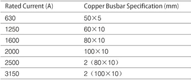
3.3 Three-phase horizontal busbars shall adopt copper busbars, featuring high mechanical strength and good heat dissipation. The horizontal copper busbar bars for switchgear shall be selected (see table)
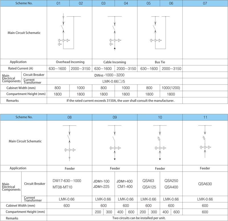
Main Circuit Schematics
Phone: +86 18066329111
E-mail: liuran8020gmail.com
Address: Yanpan Industrial Zone, Yueqing City, Zhejiang Province









 Español
 Portugues
 Pусский
 العربية
 Türk dili
 Indonesia
 Tiếng Việt
 қазақ
қазақ فارسی
فارسی українська
 беларускі
 Filipino
 o'zbek
 български
 тоҷикӣ
 kiswahili
 Монгол
 አማራ
አማራ Ilocano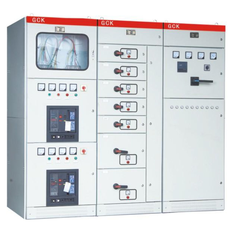



 WhatsApp
 Phone
Phone E-mail
 Message