Main Functions
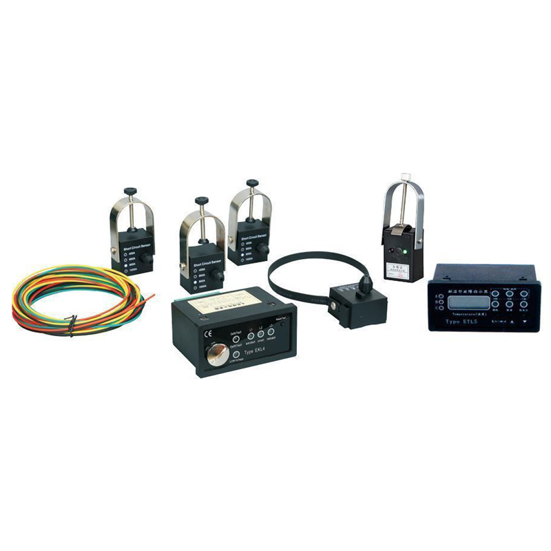
● Short-circuit alarm indication: The short-circuit sensor detects line current during operation. When a short-circuit fault occurs and meets the judgment conditions, it sends an alarm signal.
● Ground fault alarm indication: The ground fault sensor detects zero-sequence current during operation. When a ground fault occurs and the fault current exceeds the set value, it sends an alarm signal.
● Over-temperature alarm indication: The temperature sensor detects the temperature near the cable head and transmits the data to the host via optical fiber in a very short time. When the cable temperature reaches or exceeds the alarm set value, the host sends an alarm signal and closes the contacts.
● Temperature and current display: The integrated sensor monitors the temperature and current at the monitoring point, and transmits the data to the host via optical fiber at a certain frequency. After receiving the signal, the host displays the data on the LCD screen. (Phase current and temperature can be viewed by pressing the ▲▼ keys) (Current display is optional)
● RS485 communication: After the indicator generates short-circuit or ground fault alarm signals, it can output the fault status remotely via RS485 communication cable. When no fault occurs, the line load current and monitoring point temperature are periodically reported to the host computer via RS485 cable. (Optional function)
Technical Parameters
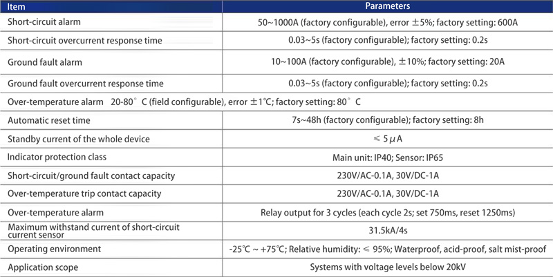
Ground Fault Alarm Indication: The ground fault sensor is installed on the non-shielded part of the three-phase cable branch to detect the zero-sequence current value of the three-phase cable. When the value reaches or exceeds the set ground fault current threshold (which can be preset at the factory according to user requirements), the ground fault sensor sends an alarm signal and transmits it via optical fiber to the indicator host for ground fault alarm indication.
Installation Method
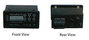
1.Installation of the Indicator Host
The indicator host is mounted on the front panel of the distribution cabinet.
To remove the host, press the metal spring clips on the host housing.
Cutout dimensions: 91.5mm (tolerance: ±0.3) × 43mm (tolerance: ±0.3)
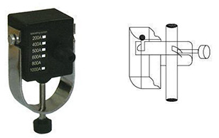
2.Installation of the Short-Circuit Fault Sensor
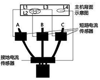
Fit the cable clamp around the cable, then insert the two hooks of the sensor along the opening of the clamp. After connecting the sensor and the clamp, tighten the fixing screw on the clamp to secure the sensor to the phase cable. The short-circuit fault sensor must be installed on the branch phase cable of the ring main distribution line and must be firmly sleeved on the tested cable to prevent the optical fiber interface from loosening or breaking due to sensor sliding.
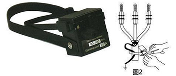
3.Installation of the Ground Fault Sensor
Loosen the screw on the magnetic ring, wrap the non-shielded section of the three-phase cable, then tighten the screw on the magnetic ring. Tighten the strap on the sensor to fix it firmly on the three-phase cable to prevent movement.
4.Connection of the Signal Optical Fiber
Loosen the nut on the fiber optic socket, insert one end of the optical fiber into the socket until the fiber tip is fully seated, then tighten the nut until the fiber is secure. Connect the other end of the fiber to the corresponding socket on the indicator host using the same method and lock it in place. Both sensor connections to the host must be firm to prevent loosening and disconnection, ensuring normal operation of the indicator.
Note: The ends of the optical fiber are specially treated. Do not cut them arbitrarily, as this will affect the normal operation of the indicator!
5.Connection of Remote Signals

Phone: +86 18066329111
E-mail: liuran8020gmail.com
Address: Yanpan Industrial Zone, Yueqing City, Zhejiang Province









 Español
 Portugues
 Pусский
 العربية
 Türk dili
 Indonesia
 Tiếng Việt
 қазақ
қазақ فارسی
فارسی українська
 беларускі
 Filipino
 o'zbek
 български
 тоҷикӣ
 kiswahili
 Монгол
 አማራ
አማራ Ilocano



 WhatsApp
 Phone
Phone E-mail
 Message